Thursday, November 29, 2007

ongoing research


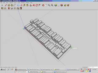
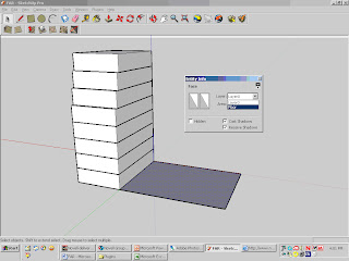
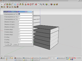
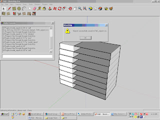
script used: grow.rb http://www.crai.archi.fr/rubylibrarydepot/ruby/EM/Grow.rb

ongoing research to develop zoning regulations independent of Cartesian geometry

Tuesday, November 20, 2007

15 minute randomized block


Parametric Zoning Envelope Columbia GSAPP
Mini-Tutorial.1 15-minute block


Topics: randomization, lot coverage, commercial overlay, city block

Scripts to load: IncRandomPushPull

All the geometry in this tutorial will be built from the rectangle tool.

We will start with the dimensions of a lot, copy that lot to make a full block, and then place randomized building envelopes on this field.


Using the rectangle tool, make a rectangle about 20’ by 90’. Copy that rectangle 24 times, being careful to snap the endpoints together (just copy once by holding down the control button with the Move tool and hitting “x 24” and the enter key afterwards)


Once you have 25 lots lined up, copy that row of lots to make the other side of the block.


Make a rectangle about 60 feet deep and copy it across


Select all new rectangles (click each one with Shift key held down) and click open RandomPushPull function from Plugins

The PlugIn’s Z axis is upside down, so make sure to include the negative sign.


Now turn around to the back of the “buildings” to make first floors. On the back face of one building, make first story rectangle about 10’ in height. Copy across the others.

Delete any extra lines.

Select all first floor rectangles and apply RandomPushPull from 0 to -30’


Repeat same process on other half of block.


On the other side of the block, start again with 60’ deep rectangles, extrude randomly from 30’ to 70’. Then draw the 10’ first floor rectangle on the rear face and copy across, extruding all 0’ to 30’.


Select the first floors on either side of the block to extrude, since rear yard requirements don’t apply to corner lots. Extrude 20’ to 60’


Move each façade of corner lot envelopes to the rear lot line, to close off the block


Put 2 squares about 15’ x 15’ at each corner of the block, to establish dimension of sidewalk


Draw a rectangle from endpoint to endpoint to create 15 foot perimeter sidewalk


Does this look like a typical New York City block? Why or why not? Explain, how, using the same tools, a more realistic block could be generated. What steps in the above process would change?

Ruby script editor

Ruby script editor: http://ruby.about.com/gi/dynamic/offsite.htmzi=1/XJ&sdn=ruby&zu=http%3A%2F%2Fwww.scintilla.org%2FSciTE.html


(SciTE is a SCIntilla based Text Editor.)

FAR output to excel

Parametric Zoning Envelope Columbia GSAPP
Tutorial2 FAR xls


Topics: Microsoft Excel, FAR, sky exposure plane

Scripts to load: shapes.rb, Parametric.rb, model_report.rb, Grow.rb


Name your file FAR_yourname. (The model_report script will not work within an untitled file)


Create a box (from Draw -> Shapes -> Box) with dimensions Width 30’ Depth 50’ and Height 10’.

Using the control key with Move tool, Copy the box up 5 times (so that you have 6 floors total reaching 60’)

Select the top box and, using the Grow tool under Plugins, apply the following settings


Be careful to reset default numbers to 0 where transformations are not being applied

Question: Which District envelope is this similar to now?


Make a plane 50’ x 65’ by Create Box with Height 0’.


Move the plane adjacent to the base of the first building and Explode it (right click).


Open Layers menu under Windows. Select Layer 0 and change the name to Floor.


Right click on the plane to bring up its Entity Info window. Change Layer from Layer 1 to Floor layer.


Use the Rectangle tool to make a side wall between the first and second planes.


Select both the side wall and plane and make 5 copies up, snapping to the Endpoints of the adjacent building as a reference.


Again selecting both the sidewall and the top plane, Apply the Grow function to the top floor, just as we did the adjacent Box. The same settings will appear in the Grow window.


Under Tools, select Model Report. Select Excel as export format.


If the success message above does not appear, open the Ruby console and repeat the same procedure, then troubleshoot.

Open the Excel file. Can you find the total Floor Area? What additional data would you need to calculate FAR?

Friday, November 16, 2007

Scripts for polygon geometry - FAR and envelope

Parametric Zoning Envelope Columbia GSAPP
Tutorial 1 Polygonal Modeling + Scripting

Topics: FAR, envelope, constraints and variables, scripting polygon geometry

Scripts to load: zone.rb, parametric.rb, shapes.rb

Make a box from the Shapes function under Draw (Draw -> Shapes -> Box) with dimensions

Width 50’ Depth 50’ Height 10’


Now make an identical-looking object as a 4 sided prism (Draw -> Shapes -> Prism) with Radius 35’ and Height 10’

Move the Box so that it is 30 feet or so apart from the Prism (not overlapping)

Copy both twice (Select both objects, hold Control key with the Move tool and hit “x 2” when moving) placing copies about 100 feet from originals


Explode each of the 4 copies AFTER copying


Do NOT explode originals

Manipulate the first pair of copies
- move the top face up and down
- selecting a corner vertex and move it (see image below)
- select a perimeter line along the top face and move it (or try to)
- selecting one side face and moving it


Note how the two objects in your model respond differently to each manipulation

From the next pair of exploded copies (non-distorted copies) select just the top face and copy-move up about 10’ to create 8 more planes (“x 8”)


Now you have two 9-storey “buildings”

With the Rectangle Tool click on the top left and bottom right corners to make a façade plane for each building

Repeat this on an adjacent side

Copy-Move both “buildings” and place the copies about 100 feet to the right of the originals. (Note: Your final screen will look a little different than mine, since I didn’t do this.)


Select a rectangle from the façade. Note that now the faces are divided up between each “floor.”

Based on what you noticed with the initial Box and Prism, how do you think the two “buildings” will respond differently to manipulations of “façade” planes?


Move planes in the façade
What’s the difference in response?
What are the variables and constraints in each “building”?
Describe a situation in which the Box methodology of construction would be more efficient than Prism, and vice versa.


What do you think will happen when you rotate the façade in each “building”? Try it

**** Post your SketchUp file to CourseWorks in SharedFiles *****

Extra credit:

What would be the exact dimension of the 4-sided Prism “Radius” to make it equivalent to the 50 by 50 Box?

Super Extra Credit:

What in the scripting of Prism and Box functions makes the two Shapes respond differently after the group is exploded? How would you script a “Box” Shape (ie with height, width and length) that would act like the 4-sided Prism? i.e. Could this behavior only work for square-faced cuboids?

Thursday, November 15, 2007

Parametric Zoning Envelope, GSAPP Fall 2007

Student Work:


Rob Viola, GSAPP Fall 2007


Matthew Roe, GSAPP Fall 2007


Alexander Maisuradze, GSAPP Fall 2007


Parametric Zoning Envelope Intro


student work by Tony Tolentino, GSAPP Fall 2006


The course teaches 3D visualization techniques in relation to urban planning. Working from very basic geometric components, students generate a spatial system. The New York City Zoning Resolution provides the framework for geometric investigation. Height limits, sky exposure planes, setbacks, side-yards and other points of spatial regulation are defined as parameters in the production of a 3D system. The course recognizes that professional city planners are increasingly expected to edit and even produce 3D models.


student work by Gabe Llyod, GSAPP Fall2006


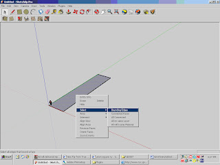
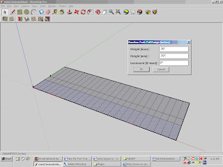
Classes cover introductory techniques for 3dstudio Max, Google SketchUp, as well as Microsoft Excel. Students who have no experience in 3D modeling software will learn to produce 3D volumes in Google SketchUp, connecting these operations with specific variables in the zoning envelope. The course does not focus on rendering techniques – screenshots will be used to present coursework. Final project combines both text (spreadsheet) and 2D images to construct a text amendment for 1 residential or commercial zoning district (R6, R7-1, C2-6, etc) in the New York City Zoning Resolution. Students work individually.

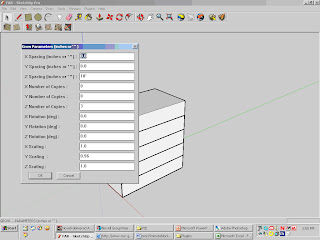
Students with more experience in 3dstudio Max or other parametric modeling software will have the option of developing an animation or zoning envelope script as a final project. Guidance for Maya is available for students with previous modeling experience.

The course welcomes architects!

Although the workshops will be geared towards Google SketchUp and the fundamentals of 3dstudio Max and Microsoft Excel, the course aims to develop dialogue amongst architects, urban designers, and planners. Architects who are interested in parametric modeling will learn to deploy scripting techniques towards the analysis of New York City zoning regulations. The goal is not to model one building, but to design the possibility of a building – the zoning envelope. The potential of zoning is to generate a built environment capable of interfacing with the variability of a free market and demographic change, as well as the constraints of socioeconomic policy, ecological impact, and other public concerns. The surface of the ground-plane – segmented into tax lots, streets, and sidewalks – forms the continuous parameter upon which zoning distributes a field of possible discrete volumes. For more advanced programmers, there are two parameters to model as constant 1) the ground-plane 2) time. Defining constraints and constants in the system becomes a matter of both policy and design.

student work by Kay Cheng, GSAPP Fall 2006